Hydraulic water pump for watering an orchard

Saw this post on facebook

(https://practicalsurvivalist.com/hydraulic-ram-pump-build/?fbclid=IwY2xjawMqpn9leHRuA2FlbQIxMQABHhYMN4EQgm-c1pbR2YRJiAGEwARHHjHNoTqUSnhEOmr_5MDh7CtiJtX_Zh3j_aem_7ZksFFw3W1z8EqtqFwGpNA#content)

CATEGORIES

How to build an Off Grid Hydraulic Ram Pump that uses no electricity to pump water

Share this DIY article on

Share on FacebookShare on Pinterest
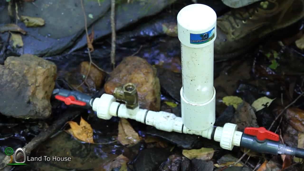
This project aims to provide a detailed guide on how to construct an efficient and reliable water pump that utilizes the natural flow of water to pump water uphill without the need for an external power source.
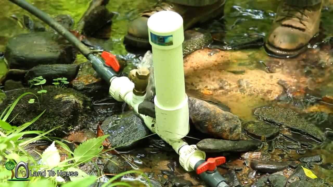
However, these sharp pressure spikes can cause significant wear and tear on the pump components, making it necessary to incorporate a pressure tank into the system.

The pressure tank acts as a buffer, smoothing out the pressure spikes and providing a more even flow rate out of the delivery pipe.

The pressure tank works by absorbing and storing excess water pressure during the spike and releasing it gradually, thus reducing the risk of damage to the pump components.
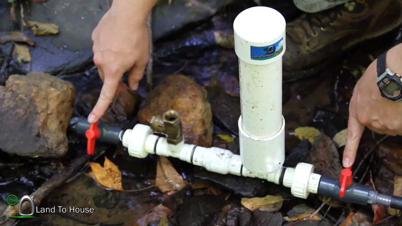
In the construction of a hydraulic ram pump system, the pressure tank is an essential component that helps to regulate the flow of water and reduce the wear and tear on the pump components.

One common material used to construct the pressure tank is PVC, due to its durability and affordability.

To assemble a one and a quarter-inch hydraulic ram pump, you will need to gather the following materials:

  • Six one quarter close pipe nipples: These components are crucial for securely connecting the different parts of the pump. They allow for a tight and compact assembly without any extra gap between the parts.

  • Two three quarter pipe nipples: These components are needed to connect the larger parts of the pump together.

  • Two one and a quarter ball valves: These valves are used to control the flow of water through the pump. They ensure that water is flowing in the correct direction and help regulate the pressure within the pump.

  • Teflon pipe tape: This tape is used to ensure that all the components are tightened up properly and to prevent any leaks.

  • A couple of wrenches: These tools are essential for tightening and securing the different components of the pump together.
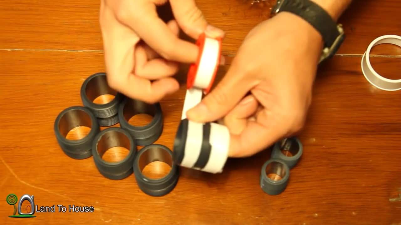
STEP 2 : SEALING THE PIPE NIPPLES

After gathering all the required materials, the next step in assembling the hydraulic ram pump is to prepare the pipe nipples by applying Teflon pipe tape.

Begin by taking the Teflon tape and wrapping it clockwise around the one-inch and three-quarter pipe nipples.

Ensure that the tape is wrapped tightly and evenly around the threads to create a smooth, even seal. This step is important to ensure that the components do not unscrew or loosen during operation, and to prevent leaks.

The Teflon tape allows the components to be screwed together in a more fluid manner and helps to create a better seal.
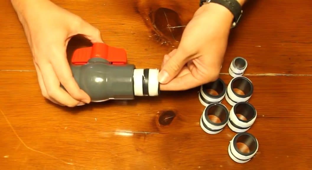
STEP 3 : ASSEMBLING THE HYDRAULIC PUMP

To proceed with the pump assembly, take your one and a quarter ball valve and a pipe nipple and screw them together tightly.
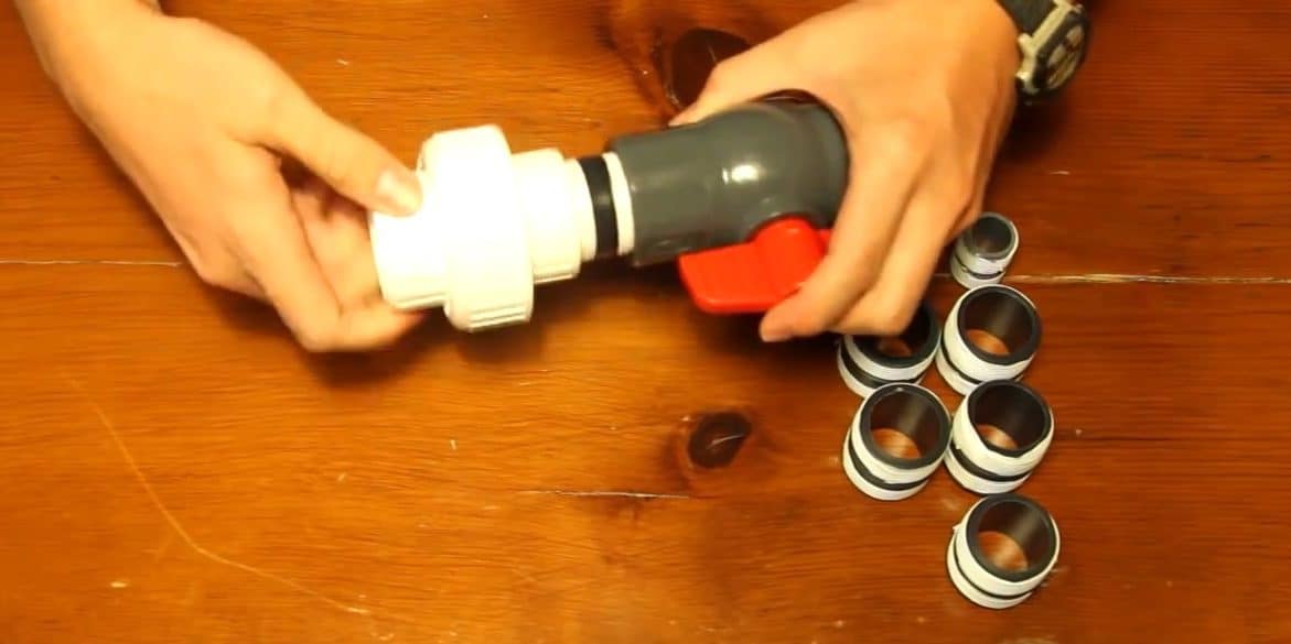
Then, connect the one and a quarter union to the other end of the taped nipples using another pipe nipple.
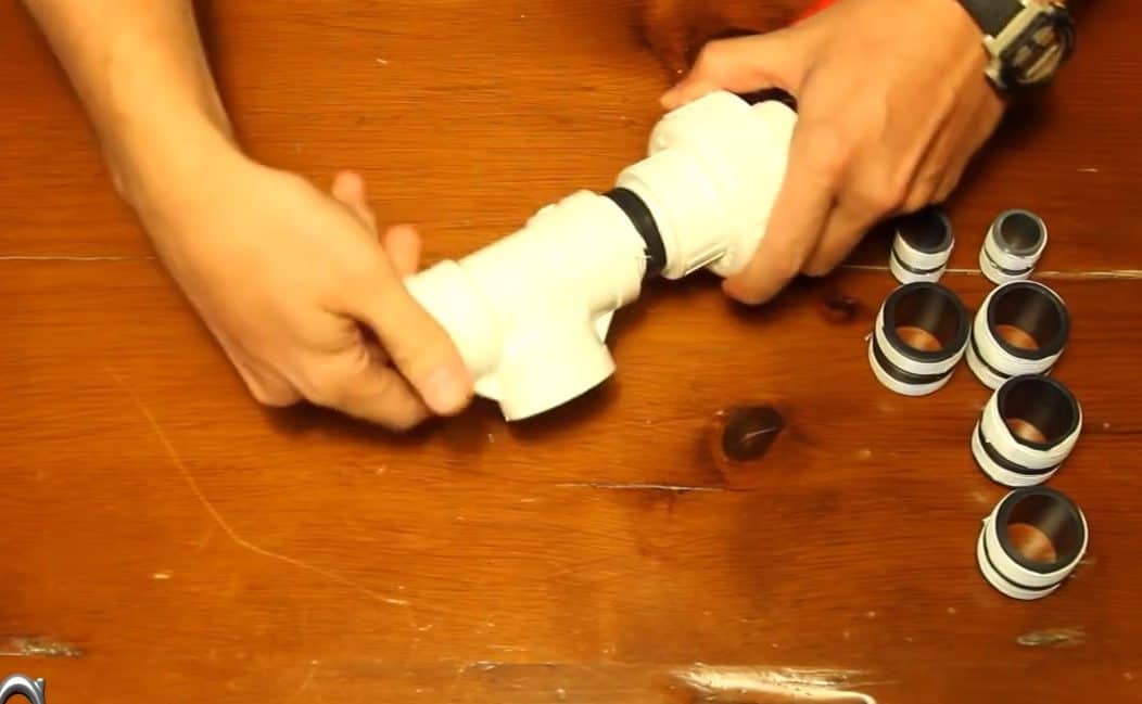
The next step is to attach a spring check valve to this unit, making sure that the flow is pointing away from the components we just put together. Note that there is an arrow on these valves that indicates the flow direction.
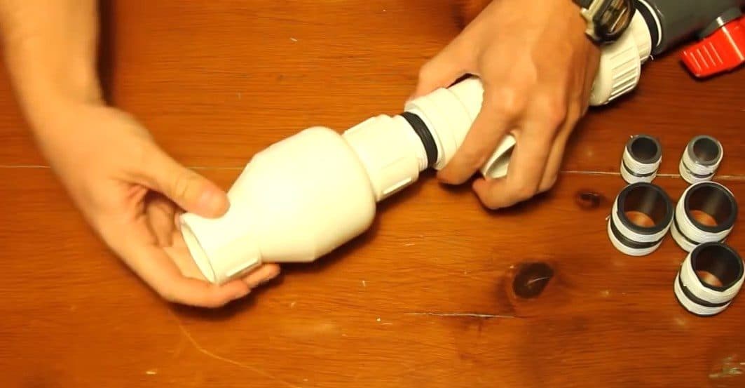
Connect another PVC tee to the valve through a nipple, and then attach a threaded bushing to the end of that second tee.
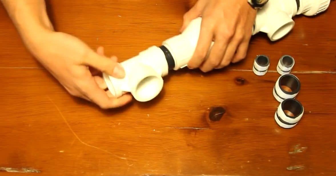
Repeat this step by connecting another PVC tee to the valve through a nipple and attaching another threaded bushing to the end of the tee.

On the three-quarter bushing, put one of the three-quarter pipe nipples. From that pipe nipple, attach the other three-quarter-inch union.

Then, connect a three-quarter ball valve to this end using another pipe nipple.
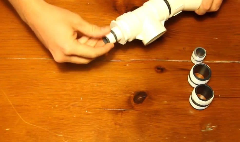
A three quarter ball valve is connected to this end through another pipe nipple.
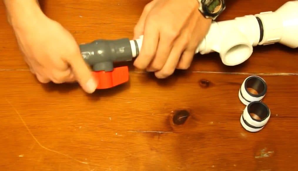
Attach the swing brass/stainless steel check valve to the first PVC tee with the help of another pipe nipple. When connecting the check valve, make sure that the door or flapper is going to fall open from gravity. So, screw it onto this pipe nipple with the door hanging open.
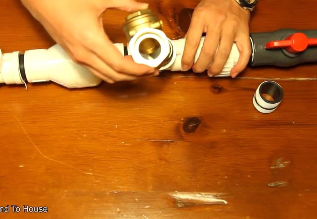
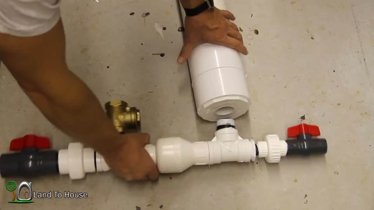
Finally, connect the second PVC tee to the pressure tank using another pipe nipple. Ensure that both tees are facing in the same direction
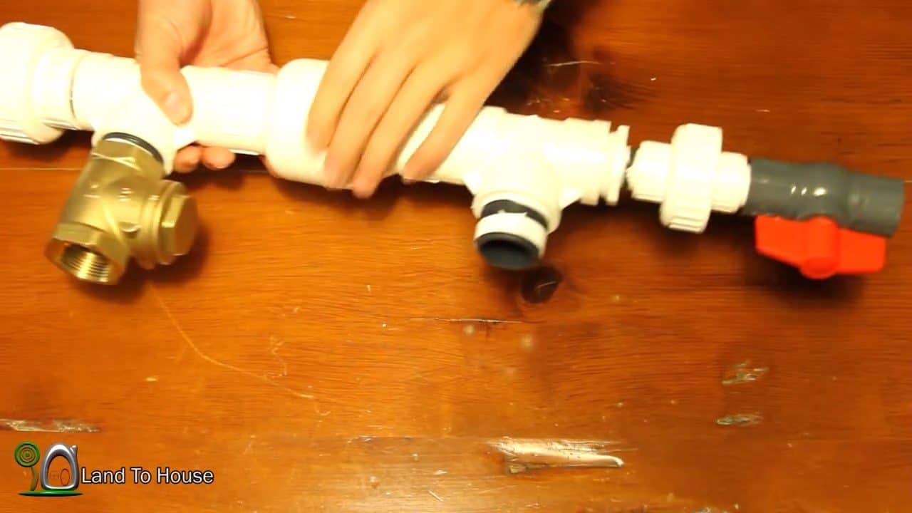
STEP 4 : BUIDLING THE PRESSURE TANK

The pressure tank is a crucial component of the one and a quarter-inch hydraulic ram pump. To construct the pressure tank, you’ll need a few materials: a four-inch PVC schedule 40 pipe, a four-inch coupling, a four-inch socket to one and a quarter threaded bushing, a four-inch cap, and a bicycle inner tube.
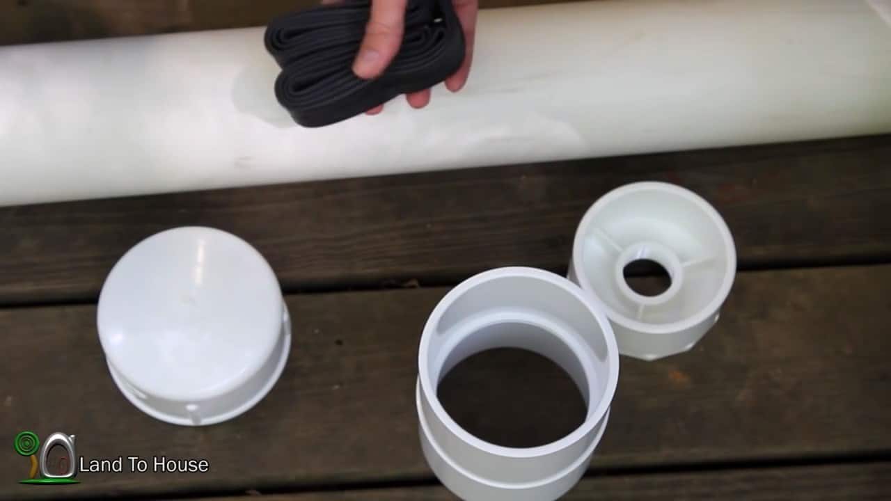
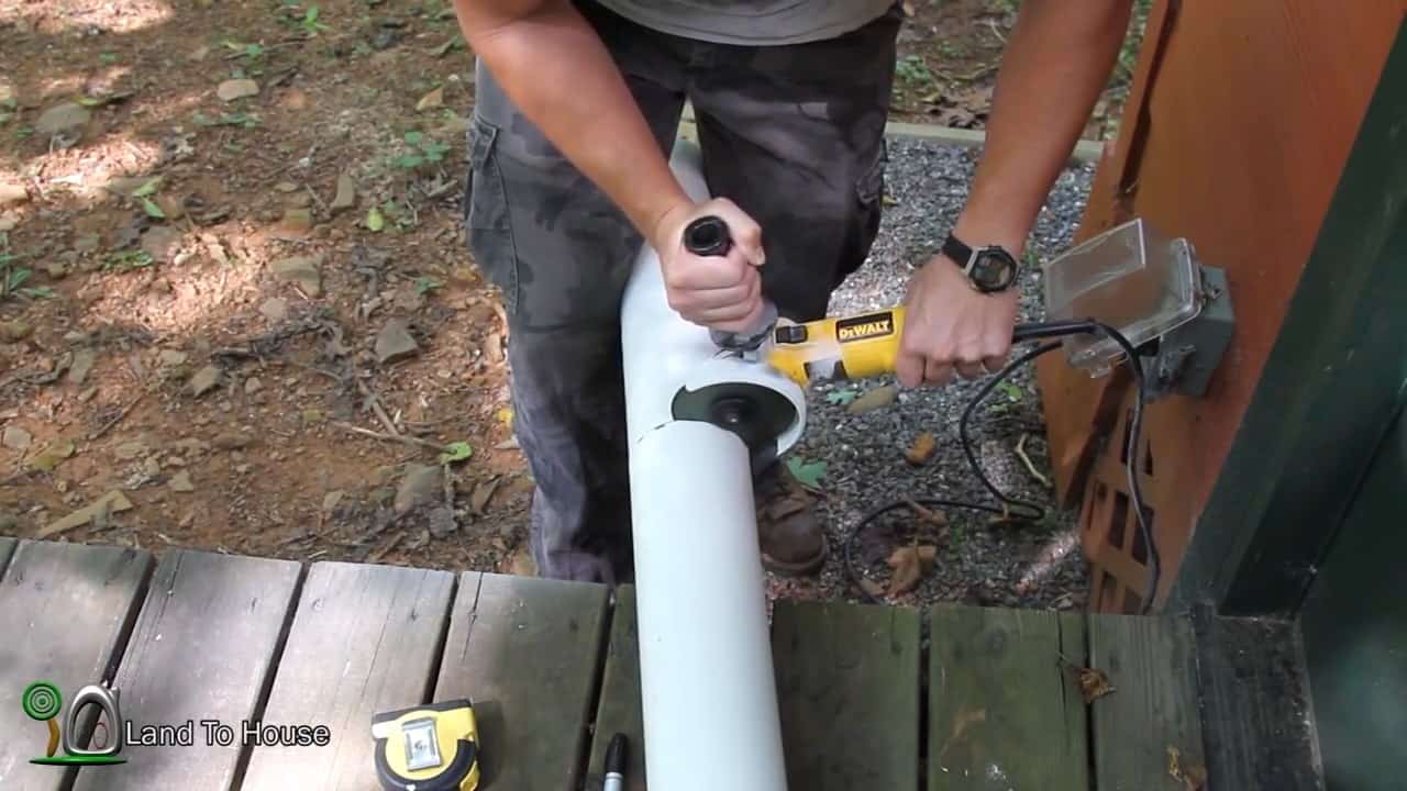
Using an angle grinder, cut a 17-inch long section from the four-inch PVC schedule 40 pipe. It is important to ensure that the cut is clean and straight for the optimal functioning of the pump.

Once you have the pipe section, you can proceed to assemble the pressure tank.
To assemble the pressure tank for the one and a quarter-inch pump, first, apply PVC cement to the inside of the coupling. Then, insert the 17-inch PVC schedule 40 pipe into the coupling.

It is important to make sure that the pipe fits tightly into the coupling, so that it does not come loose during use.

Next, attach the threaded bushing to the other end of the coupling. This threaded bushing will allow the tank to connect to the pump assembly.
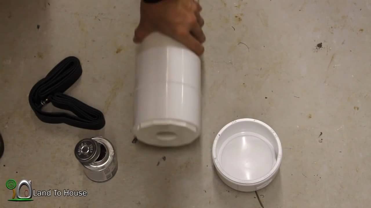
After assembling the pressure tank, the next step is to insert the bike’s inner tube. This is done by stretching the inner tube over the open end of the coupling and securing it in place with a zip tie.

Make sure that the inner tube is stretched tight and without any wrinkles or folds.Once the inner tube is securely in place, it’s time to attach the pump to it.
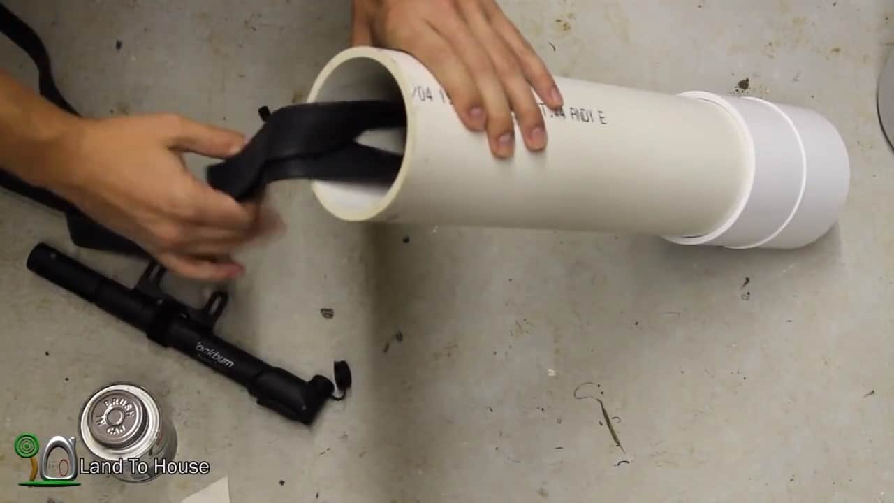
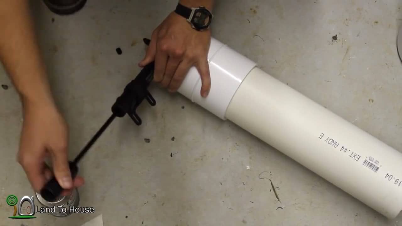
To pressurize the pressure tank, begin by inserting the bicycle inner tube into the tank through the threaded bushing.

Make sure that the tube is inserted properly and not twisted. Use a bicycle pump to inflate the inner tube.

Pump the tube until it feels tight and firm. Check the pressure with a pressure gauge to ensure that it is within the recommended range.

Once you are satisfied with the pressure, insert the cap into the end of the pipe and coat the threads with PVC cement.

Screw the cap onto the pipe, tightening it securely to create a seal. Finally, apply PVC cement around the joint where the cap meets the pipe to ensure that it is completely sealed.

Allow the cement to dry completely before moving onto the next step
STEP 5 : CONNECTING THE PRESSURE TANK AND INSTALLING THE RAM PUMP

The final step in the assembly process is to attach the pressure tank onto the threaded nipple connected to the second PVC tee on the pump. Make sure that it is tightly secured to prevent any leaks.

Once the pump is fully assembled, it’s time to install it near the water source. It’s important to note that this one and a quarter inch pump requires a minimum of eight gallons per minute to operate.

It’s crucial to ensure that the water source provides enough flow rate to make the pump functional.

It’s also important to note that the amount of water that can be obtained at the delivery point increases with larger pump sizes. If the desired water output is high, consider using a larger pump.
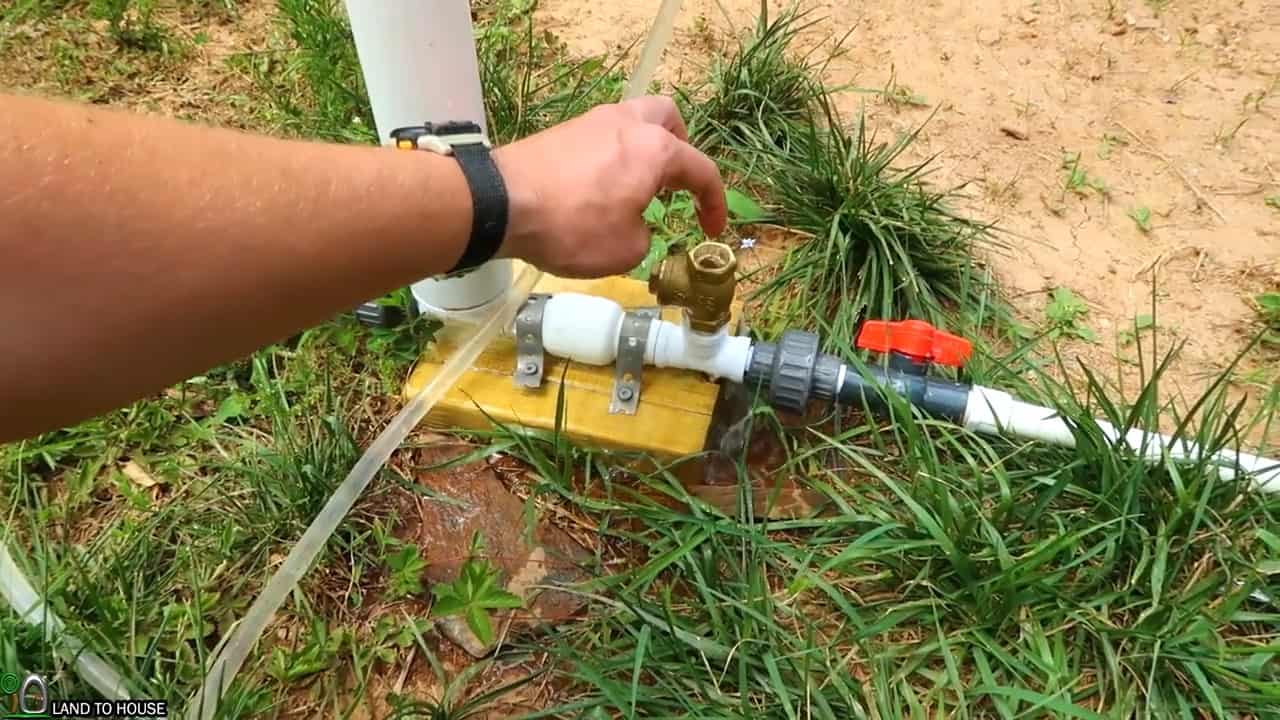
To initiate the pumping process, it is essential to ensure that the ball valve for the delivery pipe is shut, while the ball valve for the drive pipe is open.

Next, push the waste valve down until all the air inside the drive pipe is removed.

As water flows down the drive pipe, it hits the check valve with force, causing it to shut down. This action generates a pressure wave that is then propelled up the drive pipe.

However, if this pressure wave encounters an air pocket, the pump will come to a halt.

Therefore, it is crucial to ensure that there is no air trapped in the drive pipe to guarantee the smooth operation of the pump.
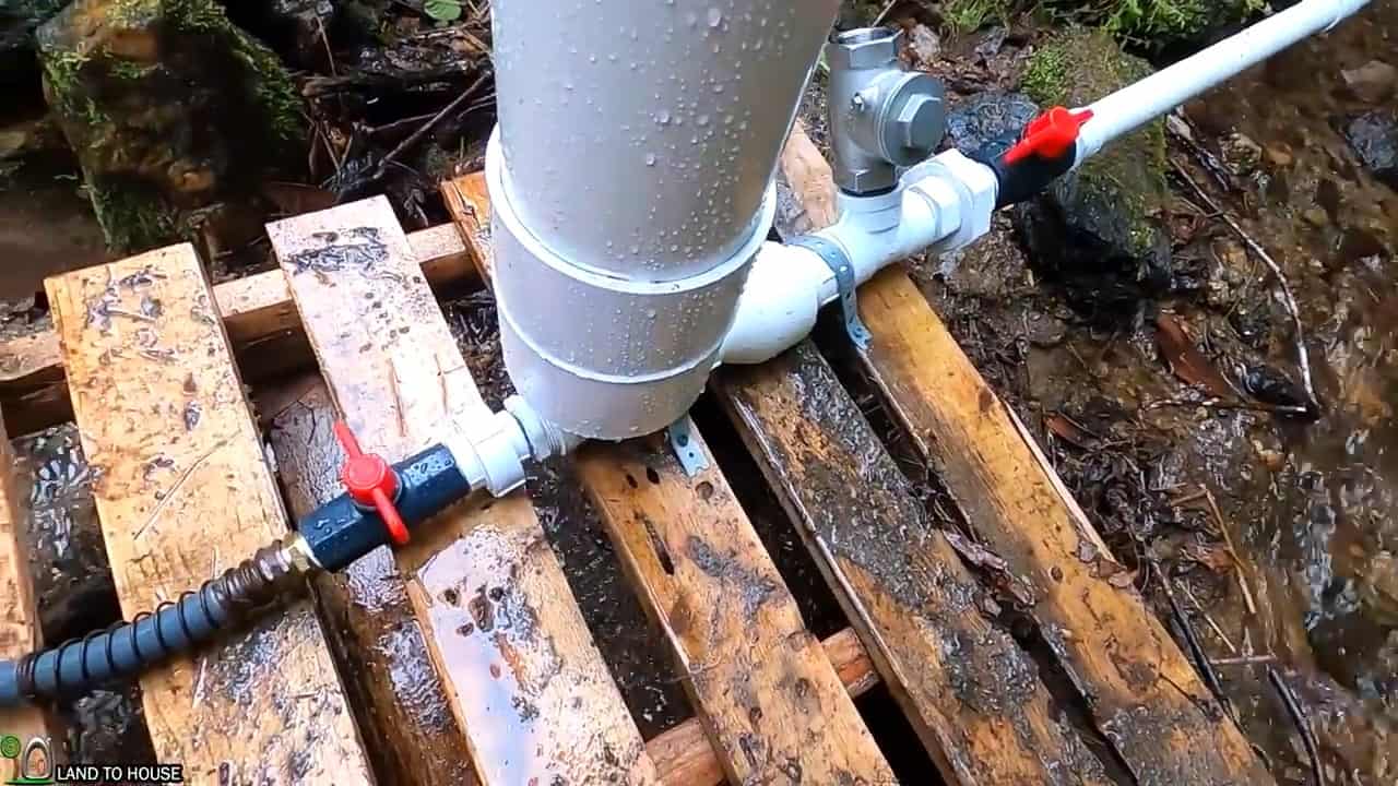
To prime the pump, begin by manually opening and closing the valve a few times until the pump starts to work automatically. It might take a few tries to get the right rhythm, but once you do, you should see the pump begin to function properly.

After the pump has been running for a minute or two, you can slowly open up the delivery pipe valve to allow the water to start flowing out.

It is important to note that you should not open the delivery pipe valve too quickly, as this can cause a sudden drop in pressure that could damage the pump.

Instead, open the valve slowly and steadily to allow the pressure to build up gradually.

Once the pump is running smoothly and the delivery pipe valve is open, the pressure tank will start to fill up with water.

This will help to maintain a constant pressure and flow rate, even when the water supply from the source is not consistent.

Image Credits : Land to House
The instructions weren’t clear enough. I got my bicycle inner tube stuck in the ceiling fan.

2 Likes

@Audi_o_phile

Finding really great instructions is challenging. Im going to attempt to construct this thing.

1 Like

Hydraulic Ram Pumps

Publication Number: EBAE 161-92

Last Electronic Revision: March 1996 (JWM)


A hydraulic ram (or water ram) pump is a simple, motorless device for pumping water at low flow rates. It uses the energy of flowing water to lift water from a stream, pond, or spring to an elevated storage tank or to a discharge point. It is suitable for use where small quantities of water are required and power supplies are limited, such as for household, garden, or livestock water supply. A hydraulic ram pump is useful where the water source flows constantly and the usable fall from the water source to the pump location is at least 3 feet.

Principles of Operation

Skip to Principles of Operation

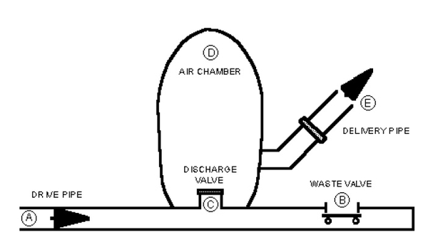
Components of a hydraulic ram pump are illustrated in Figure 1. Its operation is based on converting the velocity energy in flowing water into elevation lift. Water flows from the source through the drive pipe (A) and escapes through the waste valve (B) until it builds enough pressure to suddenly close the waste valve. Water then surges through the interior discharge valve (C) into the air chamber (D), compressing air trapped in the chamber. When the pressurized water reaches equilibrium with the trapped air, it rebounds, causing the discharge valve (C) to close. Pressurized water then escapes from the air chamber through a check valve and up the delivery pipe (E) to its destination. The closing of the discharge valve (C) causes a slight vacuum, allowing the waste valve (B) to open again, initiating a new cycle.

The cycle repeats between 20 and 100 times per minute, depending upon the flow rate. If properly installed, a hydraulic ram will operate continuously with a minimum of attention as long as the flowing water supply is continuous and excess water is drained away from the pump.

Schematic shows drive pipe (A), waste valve (B), discharge valve (C), air chamber (D), and delivery (E)

Figure 1. Hydraulic ram pump components.

System Design

Skip to System Design

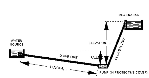
A typical hydraulic ram pump system layout is illustrated in Figure 2. Each of the following must be considered when designing a hydraulic ram pump system:

  1. available water source

  2. length and fall of the drive pipe for channeling water from the source to the pump

  3. size of the hydraulic ram pump

  4. elevation lift from the pump to the destination

  5. desired pumping flow rate through the delivery pipe to the destination.

A hydraulic ram pump system is designed to deliver the desired pumping flow rate for a given elevation lift. The range of available flow rates and elevation lifts is related to the flow quantity and velocity from the water source through the drive pipe. The mathematical relationship for pumping flow rate is based upon the flow rate through the drive pipe, the vertical fall from the source through the drive pipe, and the vertical elevation lift from the pump to the point of use. These variables are illustrated in Figure 2.

Equation 1 is used to calculate pumping rate:

Q= 1440×[E×S(L/F)]Q= 1440×[E×S(L/F)]

where:

Q=pumping rate in gallons per day (gpd)

E=efficiency of a hydraulic ram pump installation, typically equal to 0.6

S=source flow rate through the drive pipe in gallons per minute (gpm)

L=vertical elevation lift from the pump to the destination in feet F=vertical fall from the source through the drive pipe in feet.

To convert the pumping rate expressed in gallons per day(gpd) to gallons per minute(gpm), dividen by 1440. The following example illustrates an application of Equation 1.

Example.

A hydraulic ram will be used to pump water from a stream with an average flow rate of 20 gpm up to a water tank located 24 feet vertically above the pump. The vertical fall through the drive pipe in the stream to the pump is 4 feet. Assume a pumping efficiency of 0.6. What is the maximum pumping rate from the hydraulic ram pump?

In this example, E = 0.6, S = 20 gpm, L = 24 feet, and F = 4 feet. The resulting pumping rate, Q, is calculated as:

Q= 1440×[0.6×20(24/4)]=2880 gpdQ= 1440×[0.6×20(24/4)]=2880 gpd

The maximum pumping rate delivered by the hydraulic ram pump operating under these conditions is 2880 gallons per day, or 2 gallons per minute.

The example shows how the pumping rate, Q, is directly related to the source flow rate, S. If S were to double from 20 gpm to 40 gpm, the resulting pumping rate would also double to 5760 gpd, or 4 gpm.

The example also shows how the pumping rate, Q, is inversely related to the ratio of vertical elevation lift to vertical fall, L/F. If L were to double from 24 feet to 48 feet, the lift to fall ratio, L/F, would double from 6 to 12. The resulting pumping rate would decrease by half to 1440 gpd, or 1 gpm.


Table 1. Maximum pumping rates for a range of source flow rates and lift to fall ratios assuming a pumping efficiency of 0.6.

Lift to Fall Ratio L/F

(ft/ft)

Maximum Pumping Rate, Q (gpd)
Source Flow Rate, S (gpm)
2 5 10 15 20 30 50 100
2 864 2,160 4,320 6,480 8,640 12,960 21,600 43,200
3 576 1,440 2,880 4,320 5,760 8,640 14,400 28,800
4 432 1,080 2,160 3,240 4,320 6,480 10,800 21,600
5 346 864 1,728 2,592 3,456 5,184 8,640 17,280
6 288 720 1,440 2,160 2,880 4,320 7,200 14,400
7 247 617 1,234 1,851 2,469 3,703 6,171 12,343
8 216 540 1,080 1,620 2,160 3,240 5,400 10,800
9 192 480 960 1,440 1,920 2,880 4,800 9,600
10 173 432 864 1,296 1,728 2,592 4,320 8,640
12 144 360 720 1,080 1,440 2,160 3,600 7,200
14 123 309 617 926 1,234 1,851 3,086 6,171
16 108 270 540 810 1,080 1,620 2,700 5,400
18 96 240 480 720 960 1,440 2,400 4,800
20 86 216 432 648 864 1,296 2,160 4,320
25 69 173 346 518 691 1,037 1,728 3,456
30 58 144 288 432 576 864 1,440 2,880
35 49 123 247 370 494 741 1,234 2,469
40 43 108 216 324 432 648 1,080 2,160
45 38 96 192 288 384 576 960 1,920
50 35 86 173 259 346 518 864 1,728
60 29 72 144 216 288 432 720 1,440
70 25 62 123 185 247 370 617 1,234
80 22 54 108 162 216 324 540 1,080
90 19 48 96 144 192 288 480 960
100 17 43 86 130 173 259 432 864

Table 1 lists maximum pumping rates, Q, for a range of source flow rates, S, and lift to fall ratios, L/F, calculated using Equation 1 with an assumed pumping efficiency, E, of 0.6. To illustrate the use of Table 1, consider a hydraulic ram system with S = 30 gpm, L = 150 feet, and F = 5 feet. The calculated lift to fall ratio, L/F, is 30. The resulting value for Q is 864 gpd, or 0.6 gpm.

Hydraulic ram pumps are sized based upon drive pipe diameter. The size of drive pipe selected depends upon the available source water flow rate. All makes of pumps built for a given size drive pipe use about the same source flow rate. Available sizes range from 3/4-inch to 6-inch diameters, with drive pipe water flow requirements of 2 to 150 gpm. Hydraulic ram pumps typically can pump up to a maximum of 50 gpm (72,000 gpd) with maximum elevation lifts of up to 400 feet.

Approximate characteristics of hydraulic ram pumps for use in selecting pumps are listed in Table 2. The recommended delivery pipe diameter is normally half the drive pipe diameter. For the system described in the example above, the available source water flow rate is 10 gpm. From Table 2, a pump with a 1-inch drive pipe diameter and a 1/2-inch delivery pipe diameter is selected for this system.


Table 2. Hydraulic ram pump sizes and approximate pumping characteristics. Consult manufacturer’s literature for specific pumping characteristics.

Pipe Diameter Flow Rate

Min. Drive

(inches)

Min. Discharge

(inches)

Min. Required Source

(gpm)

Maximum Pumping

(gpd)

3/4 1/2 2 1,000
1 1/2 6 2,000
1 1/2 3/4 14 4,000
2 1 25 7,000
2 1/2 1 1/4 35 10,000
3 1 1/2 60 20,000
6 3 150 72,000

Schematic shows Water source, drive pipe, pump (in protective cover) , delivery pipe, and destination with elevation, E, Length (L)  and Fall

Figure 2. Hydraulic ram pump system layout

Installation

Skip to Installation

The location of the water source in relation to the desired point of water use determines how the hydraulic ram pump will be installed. The length of drive pipe should be at least 5 times the vertical fall to ensure proper operation. The length of delivery pipe is not usually considered important because friction losses in the delivery pipe are normally small due to low flow rates. For very long delivery pipes or high flow rates, friction losses will have an impact on the performance of the hydraulic ram pump. The diameter of the delivery pipe should never be reduced below that recommended by the manufacturer.

To measure the available source water flow rate from a spring or stream, build a small earthen dam with an outlet pipe for water to run through. Place a large bucket or barrel of known volume below the outlet pipe, and measure the number of seconds it takes to fill the container. Then calculate the number of gallons per minute flowing through the outlet. For example, if it takes 30 seconds to fill a 5-gallon bucket, the available source water flow rate is 10 gpm. The lowest flow rates are typically in the summer months. Measure the flow rate during this period to ensure that the year-round capacity of the system is adequate.

Purchasing a System

Skip to Purchasing a System

Prices for hydraulic ram pumps range from several hundred to several thousand dollars depending on size and performance characteristics. Contact manufacturers to determine prices and ordering specifications. Send the information listed in Table 3 to the manufacturer to assist in sizing your system properly.


Table 3: Information to provide to the manufacturer for sizing your system.

1. Available water supply in gpm

_________

2. Vertical fall in feet measured from the source water level to the foundation on which the ram pump will rest

_________

3. Distance from the water source to the ram pump in feet

_________

4. Vertical elevation lift in feet measured from the ram pump foundation to the highest point to

which water is delivered

_________

5. Distance from the ram pump to the destination tank in feet

_________

6. Desired pumping flow rate to the destination tank in gpd

_________

Acknowledgments

Skip to Acknowledgments

This fact sheet adapted from materials prepared by the California, Florida, and South Carolina Cooperative Extension Services.

Author

Greg Jennings

Professor and Extension Specialist
Biological & Agricultural Engineering”

1 Like